


![]() Laurent Brunel. Creative Common License CC-BY: Knowledge is open if anyone is free to access, use, modify, and share it — subject, at most, to measures that preserve provenance and openness.
Laurent Brunel. Creative Common License CC-BY: Knowledge is open if anyone is free to access, use, modify, and share it — subject, at most, to measures that preserve provenance and openness.
“Persistence Of Vision” systems (POV) use the fact that the human eye can’t see movements that takes less than somehow 50ms to produce. If at some point in the space you emit a flash of light and repeat it with the frequency of 20Hz the human eye (its central vision at least) won’t see the blinking. For a microcontroler like the ones used by the Arduino serie, it’s very easy to flash a LED in that way.
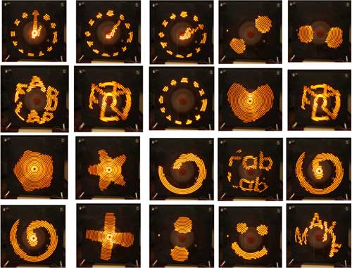
Hence it’s very cheap to produce a low resolution display with very few LEDs by placing these LEDs in a rotating arm turning with enough speed. If we manage to flash the LED repetitively at the same position after one turn of the arm the illusion is done: the eye see a continuous light just like a pixel of a display!
In this project we use 16 bright LEDs and an arduino mega. The LEDs are placed in a 3D printed rotating arm.
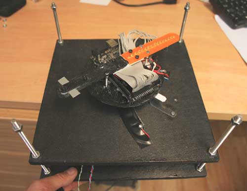
I use a recycled motor, continuous, from an old printer. With 5V it turn with a gentle speed of more or less 10 turns/s. There is a trick to carry the 5V power supply up to the embedded arduino mega: a small length of plumbing copper tube make contact with a flexible slider. The contact is greatly helped by metallic fiber from a metallic sponge. The ground itself is carried through the motor axis.
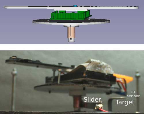
To guaranty the triggering of the LED switching such that it occurs always at the same location, a white target is placed on the main board. An infrared presence sensor is placed on the turning board. Thanks to that, one gets a precise angular absolute reference.
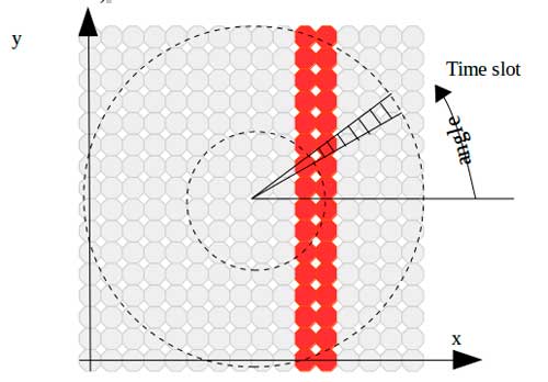
Now it’s time to code the Arduino. But first we need t create an algorithm able to transform a classic “pixelized” image, a square matrix, into correct encoding for our rotating device which basically prefer polar coordinates. Our input is an image of n pixels width and n pixels height. Our POV will cover an annular shape a ring. The ring is divided in angular sector. I call them “time slots” since the angle of this sector corresponds to a precise time of turning from our reference target to the sector. Radially, the sector is divided in 16 zones corresponding to the 16 LEDs. At the end, the image is transformed in a series of “time slots”. The arduino will just have to swich the LEDs respecting this series at the correct time et repeat for each turn. We place below a java code that allows to do this transformation.
A last nasty problem is the correct synchronization of the motor speed and the Arduino switching. Yes we could supply a very regulated current to the motor and then get a constant speed and then just put constant delays in the Arduino code. But we plan to use the basic micro-usb power supply for mobile phones and the motor speed may vary. And if the motor is slower than planned in the Arduino code the switching series may continue after the turning board has made a full turn. And the POV will trigger the next switching series only after doing an almost complete turn. The result is a almost full turn without switching any LED! -> blinking.
A first solution has been tried: thanks the IR sensor, measure the time of one full turn and calculate the timing using this information. Well it works but in some cases of speed variation it gets unstable.
O more radical solution is to use the interrupt capacity of the Arduino. The interrupt is connected to the IR sensor signal pin. The interrupt will call a method (seeMark() in the code bellow) that just change the variable “interrupt“:
void seeMark()
{
interrupt=1;
}
In the main loop we now check this variable interrupt regularly. When it seen with the value 1, it means that the POV has passed the target (angle=0) not having finished the switching series. In this case we just break the loop and start immediately another one. In this case, the timing is slightly slowed down: we assume that the motor will keep this speed.
Well guy that all. Just hack the code to check details !
—————————————————————————————-
java code to calculate the “time slots” series
——————————————————————————————
//license CC-BY Laurent Brunel
public void convertImageToSlots(int[] pixels)
{
int nbSlots=150;
//unit is led interspace
double rmin=1;//inner LED radius//in the POV frame
double rmax=16;//exterior LED radius//in the POV frame
double squareSide=2*rmax;//in the POV frame
double xcentre=rmax;//in the POV frame
double ycentre=rmax;//in the POV frame
double slotAngle=3.141592653*2/nbSlots;
int imageSize=cim2.getWidth();
int[] bb=new int[16];
for (int i=0;i<nbSlots;i++)
{
double angle=slotAngle*i;
for (int led=0;led<16;led++)
{
double rled= (rmin+led);
double x=(int)(rled*Math.cos(angle))+xcentre;//in the POV frame
double y=(int)(rled*Math.sin(angle))+ycentre;//in the POV frame
//coord in the image:
int xx=(int)(x*imageSize/squareSide);//in the image frame
int yy=(int)(y*imageSize/squareSide);//in the image frame
if (xx<0) xx=0;
if (yy<0) yy=0;
if (xx>=imageSize) xx=imageSize-1;
if (yy>=imageSize) yy=imageSize-1;
int pixValue=new Color(pixels[xx+imageSize*(imageSize-1-yy)]).getRed();
if (pixValue!=0) bb[led]=1;else bb[led]=0;
}
//byte of center
slot[2*i]=0;
for (int led=0;led<8;led++) slot[2*i]=(char)(slot[2*i]|(bb[led]<<(led)));
//byte for exterior LEDs:
slot[2*i+1]=0;
for (int led=0;led<8;led++) slot[2*i+1]=(char)(slot[2*i+1]|(bb[led+8]<<(led)));
}
//arduino code to paste in arduino IDE:
nbImages=1;
String s=””;
s+=”int nbImages=”+nbImages+”;n”;
s+=”char slot[“+(300*nbImages)+”]={n”;
for (int j=0;j<nbSlots*2-1;j++) s+=”B”+binary(slot[j])+”,”;
s+=”B”+binary(slot[nbSlots*2-1])+”n”;
if (i==nbImages-1)s+=”n”;else s+=”,n”;
ClipBoard.putText(s);
}
String binary(char c)
{
String s=””;
for (int b=0;b<8;b++) s+=((c>>b)&(1));
return s;
}
—————————————————————————————-
arduino code:
——————————————————————————————
#define nbImagesMax 8 //max 8 images stored
#define imageSize 32
#define imageSizeBytes 128
#define nbSlots 150
#define interImageTime 4000//time between each image in ms
int lastState=0;
//a time slot is defined by 2 words of 8 bits.
//the right bit (num 15) corresponds to the exterior of the POV
//the left bit (num 0) corresponds to the center of the POV
//char slot[nbSlots*2];
byte masks[8]={B10000000,B01000000,B00100000,B00010000,B00001000,B00000100,B00000010,B00000001};
//the pins connected to the LEDs, from center to exterior:
int pins[]={52,50,48,46,44,42,40,38,36,34,32,30,28,26,24,22};
int pinSensor=2;//sensor to detecd when passing agular reference (target)
int i;
// an image is encoded with 32 lines made with 8 chars-> 128 chars
int nbCharPerRow=4;
//serie of 1 image encoded as time slots:
//FabLab.png:
int nbImages=1;
char slot[300]={
B00000000,B00000000,B00000000,B00000000,B00000000,B00000000,B00000000,B00000000,B00000000,B00000000,B00000000,B00000000,B00000000,B00000000,B00000000,B00000000,B00000000,B01000000,B00000000,B11100000,B00000000,B11111000,B00000010,B11111000,B00000010,B11011000,B00000111,B10011100,B00000011,B10001100,B00000011,B00001000,B00000011,B00001100,B00000011,B10001000,B00000011,B10011000,B00000001,B11011000,B00000001,B11111000,B00010001,B11100000,B00010000,B11100000,B00011000,B11110000,B00011000,B01111000,B00011000,B01111000,B00011100,B00111000,B00011110,B00011000,B00011110,B00001000,B00011111,B00000000,B00011111,B10000000,B00011111,B10000000,B00001111,B10000000,B00001111,B11000000,B00001011,B11000000,B00001010,B11000000,B00001010,B11000000,B00001010,B11000000,B00001010,B11000000,B00001010,B11000000,B00001010,B11000000,B00001010,B01000000,B00001010,B01000000,B00001010,B11000000,B00011010,B11000000,B00011010,B11000000,B00011110,B11000000,B00011110,B11001000,B00011110,B10011000,B00011110,B00011000,B00011111,B00011000,B00011110,B01011100,B00011110,B11001100,B00010100,B11101110,B00010100,B01101110,B00000000,B01111111,B00000000,B01111110,B00000000,B00111110,B00000000,B00111100,B00000000,B00111100,B00000000,B01111000,B00000000,B01111000,B00000000,B01110000,B00000000,B01110000,B00000000,B11110000,B00000000,B11110000,B00000000,B11100000,B00000000,B01100000,B00000000,B00100000,B00000000,B00000000,B00000000,B00000000,B00000000,B00000000,B00000000,B00000000,B00000000,B00000000,B00000000,B00000000,B00000000,B00000000,B00000000,B00000000,B00000000,B00000000,B00000000,B00000000,B00000000,B00000000,B00000000,B00000000,B00000000,B00000000,B00000000,B00000000,B00000000,B00000000,B00000000,B00100000,B00000000,B01110000,B00000000,B00110000,B00000000,B00110000,B00000000,B00110000,B00000000,B00111000,B00000000,B00011000,B00000000,B00011100,B00000000,B00011100,B00000000,B00001110,B00000000,B00001110,B00000000,B00000111,B00000000,B00000010,B00000000,B00000110,B00000000,B00000100,B00000000,B00000100,B00000000,B00001000,B00000000,B00001000,B00000010,B00001000,B00000010,B01001000,B00000010,B01100000,B00000010,B11110000,B00000010,B11110000,B00000010,B11110000,B00000010,B11110000,B00000010,B11010000,B00000010,B11010000,B00000010,B10010000,B00000010,B10010000,B00000010,B10010000,B00000010,B10010000,B00000010,B11110000,B00000011,B11110000,B00000011,B11110000,B00000011,B11110000,B00000011,B11100000,B00000011,B10000000,B00000011,B00000000,B00000010,B00001000,B00000010,B00011000,B00000000,B00111000,B00000000,B00111000,B00000000,B01111100,B00000000,B11111100,B00000000,B11101110,B00000001,B11000010,B00000001,B11000111,B00000001,B11100110,B00000011,B10000111,B00000011,B10010110,B00000011,B00111110,B00000011,B00111100,B00000001,B00111100,B00000001,B00010100,B00000000,B00000000,B00000000,B00000000,B00000000,B00000000,B00000000,B00000000,B00000000,B00000000,B00000000,B00000000,B00000000,B00000000,B00000000,B00000000,B00000000,B00000000,B00000000,B00000000,B00000000,B00000000,B00000000,B00000000
};
int imageIndex=0;//index the displayed image
int previousImageIndex=-1;
int interrupt;//set to 1 by interrupt
int t=360;//delay between each slot
//the method called by interrupt
void seeMark()
{
interrupt=1;
}
void setup()
{
pinMode(pinSensor, INPUT);
for (int led=0;led<16;led++) pinMode(pins[led], OUTPUT);
attachInterrupt(0, seeMark, RISING);
}
void loop()
{
imageIndex=(millis()/interImageTime)%nbImages;
previousImageIndex=imageIndex;
if (interrupt)
{
interrupt=0;
if (lastState==LOW)
{
int c=1;
for (i=0;i<nbSlots;i++)
{
for (int led=0;led<8;led++) digitalWrite(pins[led],slot[imageIndex*300+2*i]&masks[led]);
for (int led=8;led<16;led++) digitalWrite(pins[led],slot[imageIndex*300+2*i+1]&masks[led-8]);
c=1-c;
delayMicroseconds(t);
if (interrupt)
{
t-=1;
break;
}
}
}
lastState=HIGH;
}
else
{
lastState=LOW;
}
interrupt=0;
}