This is the small version of our Corocotta series of open source 3D printers.
Effective printing volume: 200mm x 200mm x 200mm
License: CC-BY-SA :
BY: Licensees may copy, distribute, display and perform the work and make derivative works and remixes based on it only if they give the author or licensor the credits (attribution) in the manner specified by these.
SA: Licensees may distribute derivative works only under a license identical (“not more restrictive”) to the license that governs the original work. (See also copyleft.) Without share-alike, derivative works might be sublicensed with compatible but more restrictive license clauses, e.g. CC BY to CC BY-NC.)
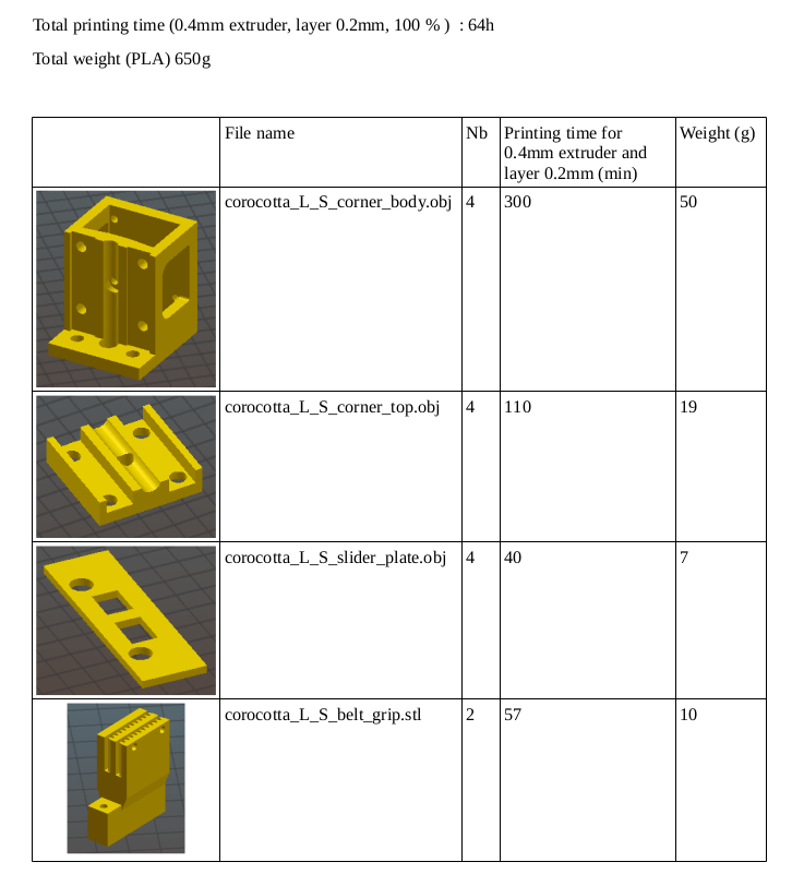
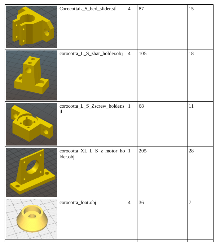
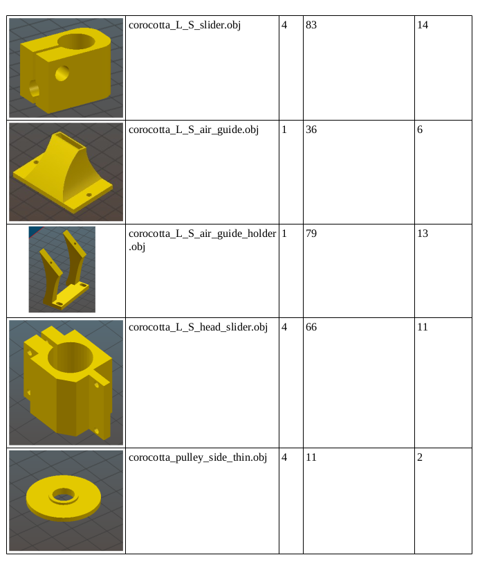
First, 3D print all the pieces (all CAD source files are here):
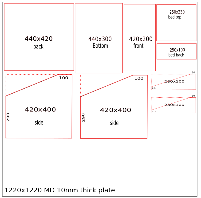
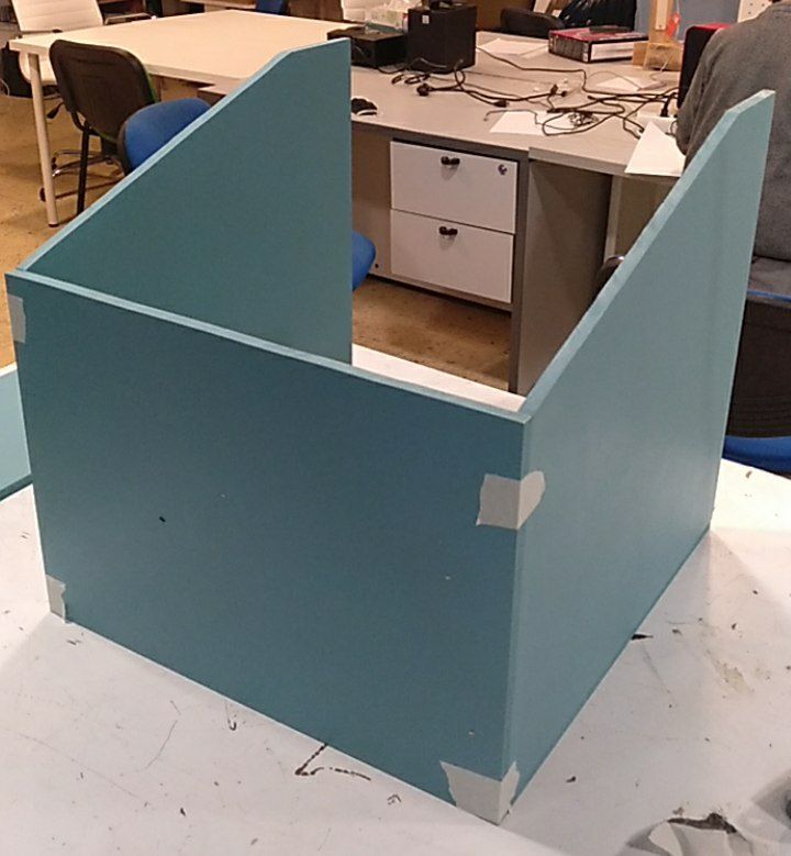
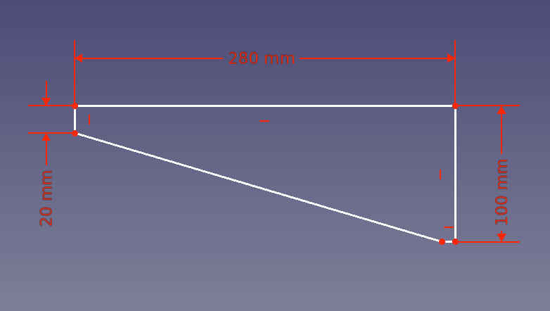
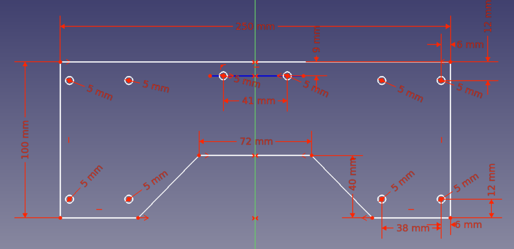
Ask your favorite shop the cutting of these MD (Medium Density) 10mm thick plates. The dimensions are in mm.
Cut by yourself the oblique lines of the side plates.
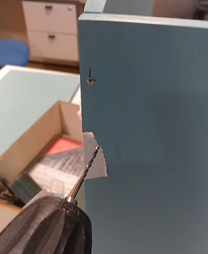
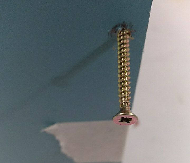
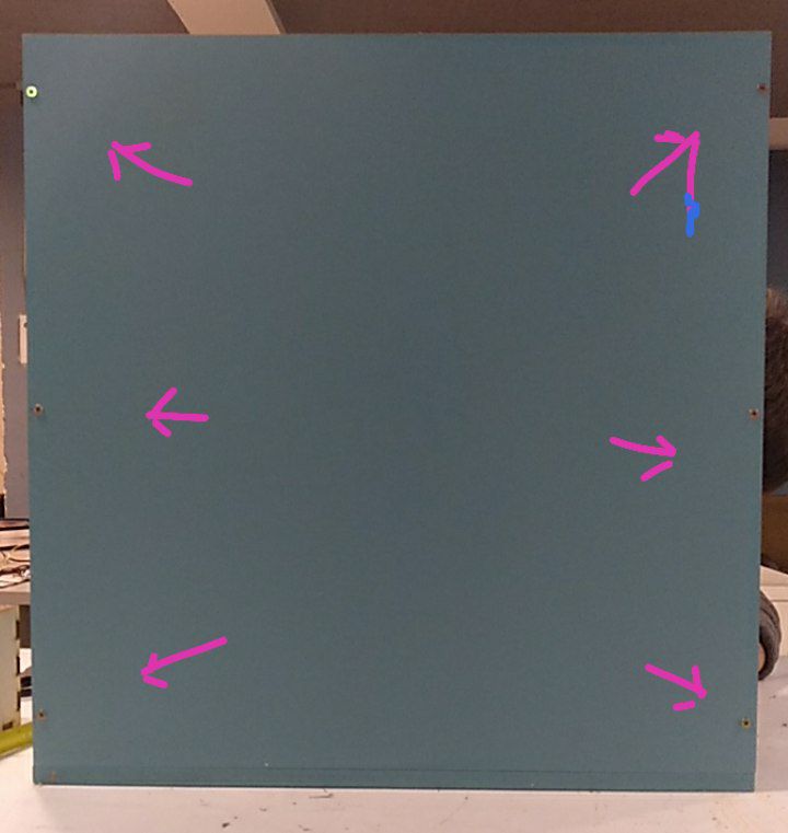
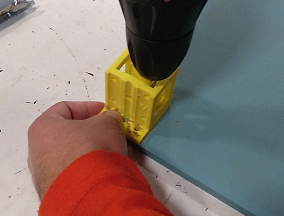
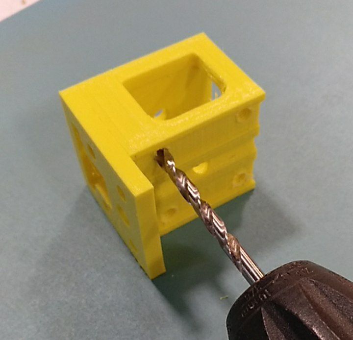
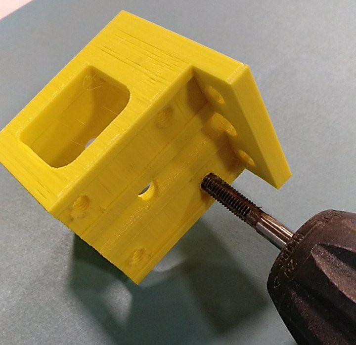
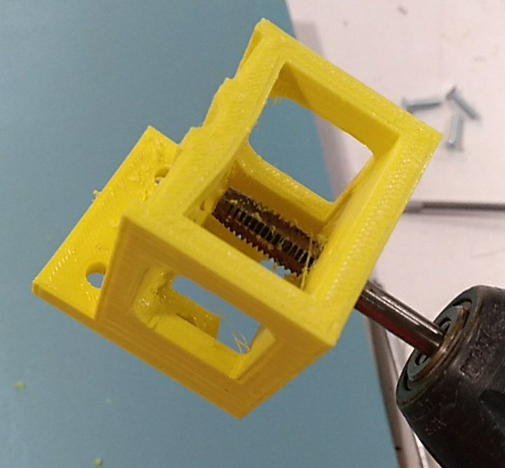
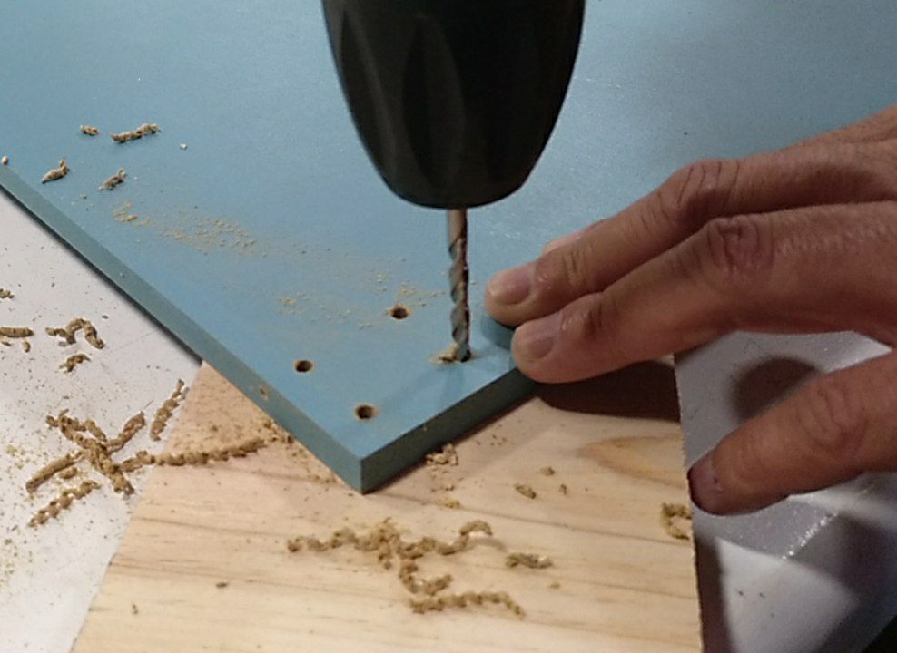
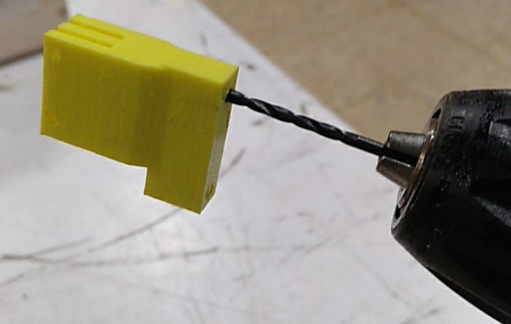
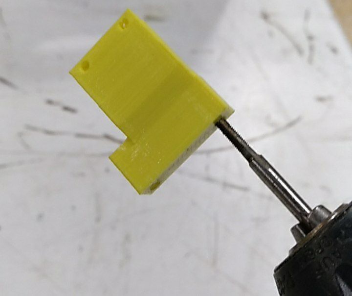
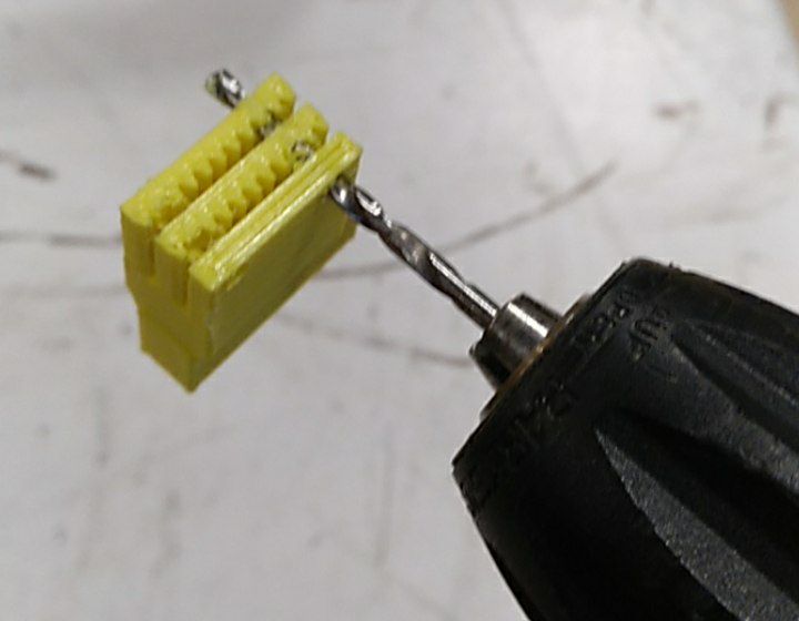
Place the plates with adhesivedrill 2mm holes (3mm for the front plate)Screws 3mm x30mm6 screws mark the holes to fix the 4 cornersDrill the 7mm holes of the cornersTap them to M8tap also the other sideDrill 4mm holes fix the corners with M5x25mm screwsdrill 2,5mm holes Drill 3,2mm holes at the upper side
Tap the 2,5mm hole with M3
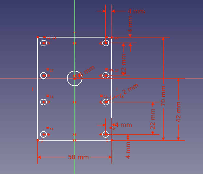
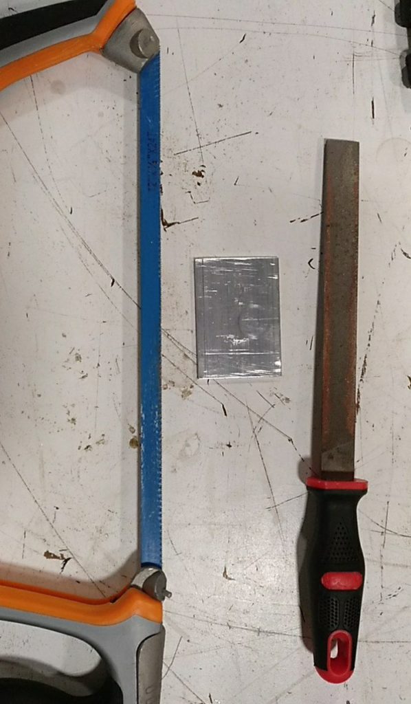
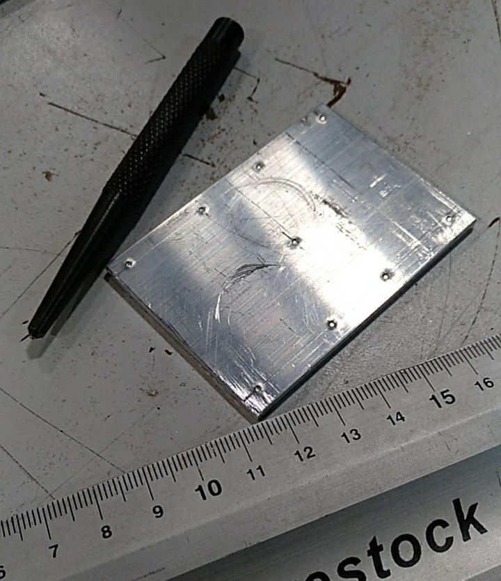
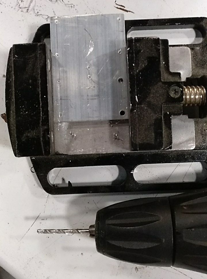
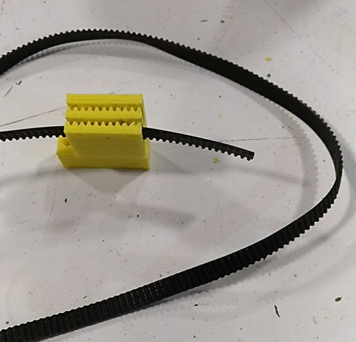
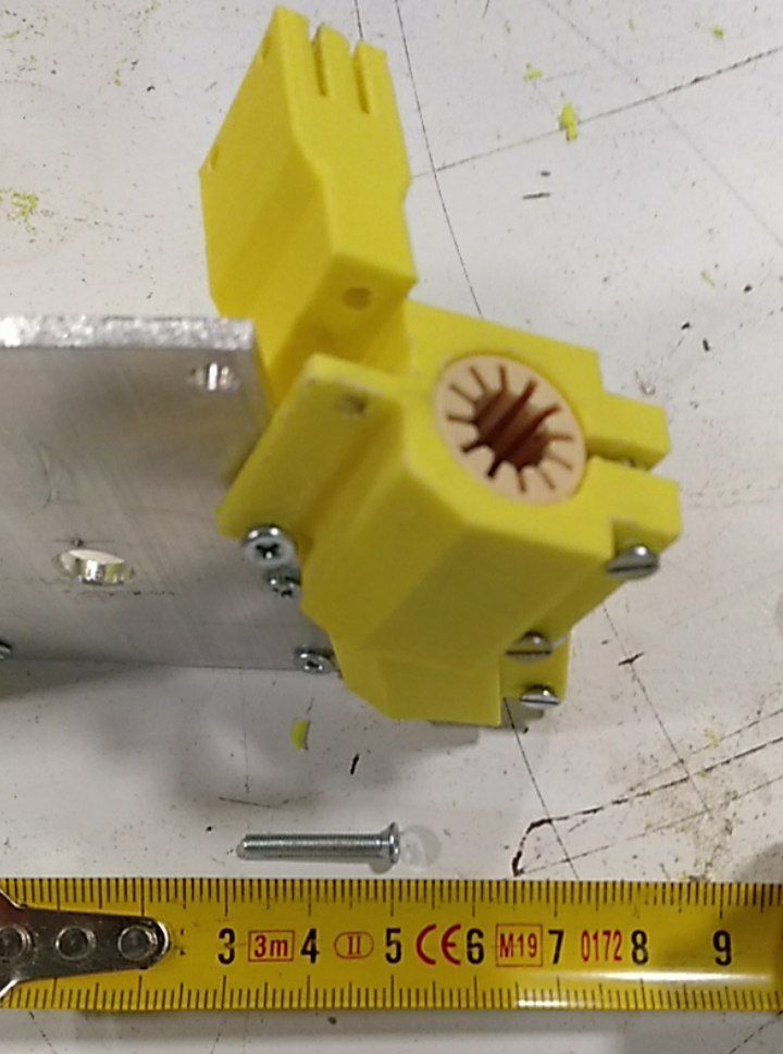
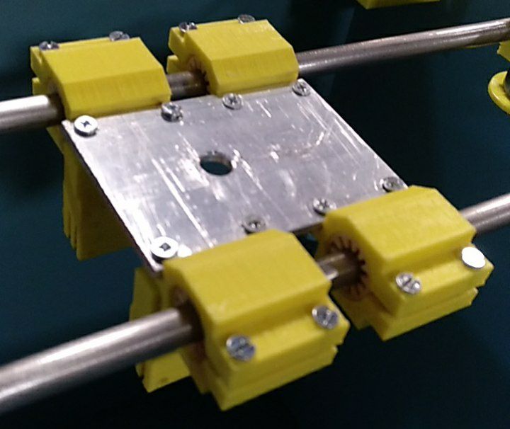
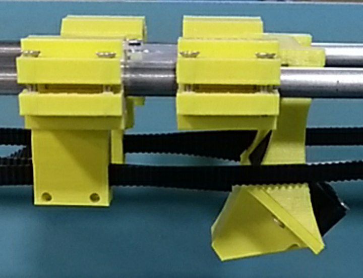
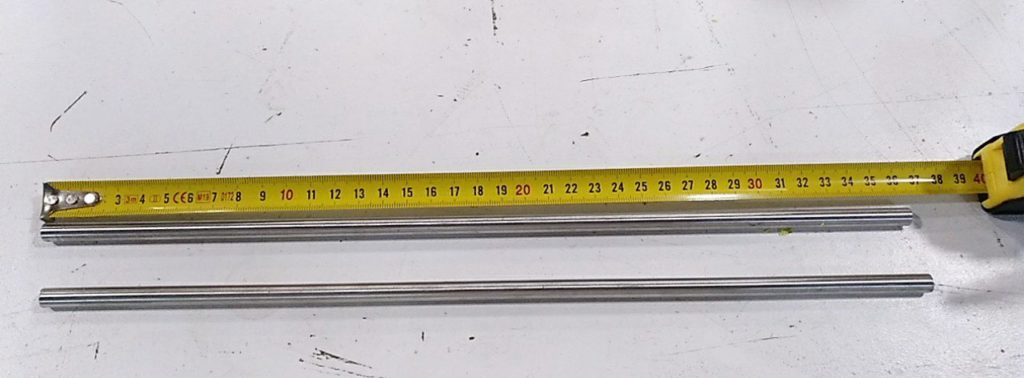
Place the 8 M3x15 screwsNow it’s time to make the aluminium head plate (3mm thick)cut the 48x70mm platemark the holes positionsDrill the 3,2mm holesPlace the X sliders, bearing and wash with M8x50 screwsCut the four 8mm diameter rods. Lengths 400mm and 337mmClean the belt holder and check.
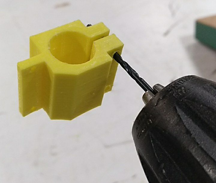
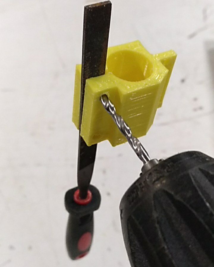
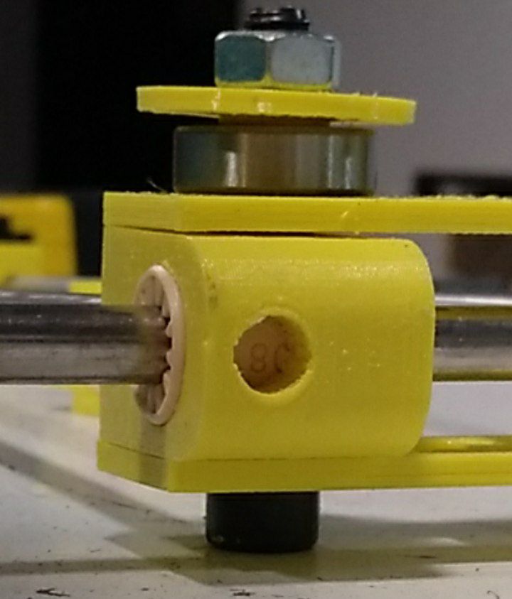
Drill the fixation holes with 2.5mm diameter. Tap with M3 (lubricate the tap with water to avoid warming). And drill 3mm holes on the side.Mount on the slider and the belt holder on the head plate
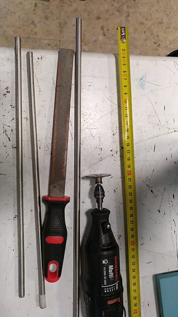
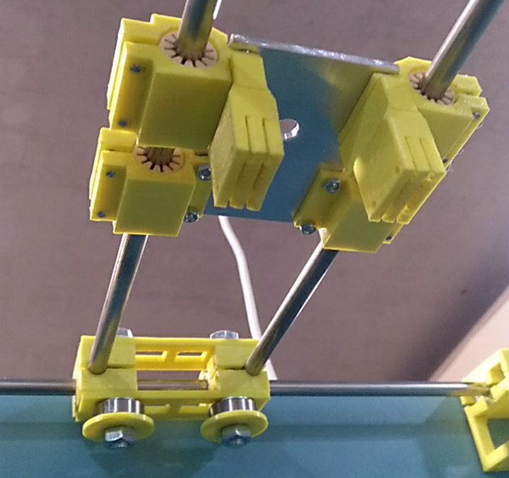
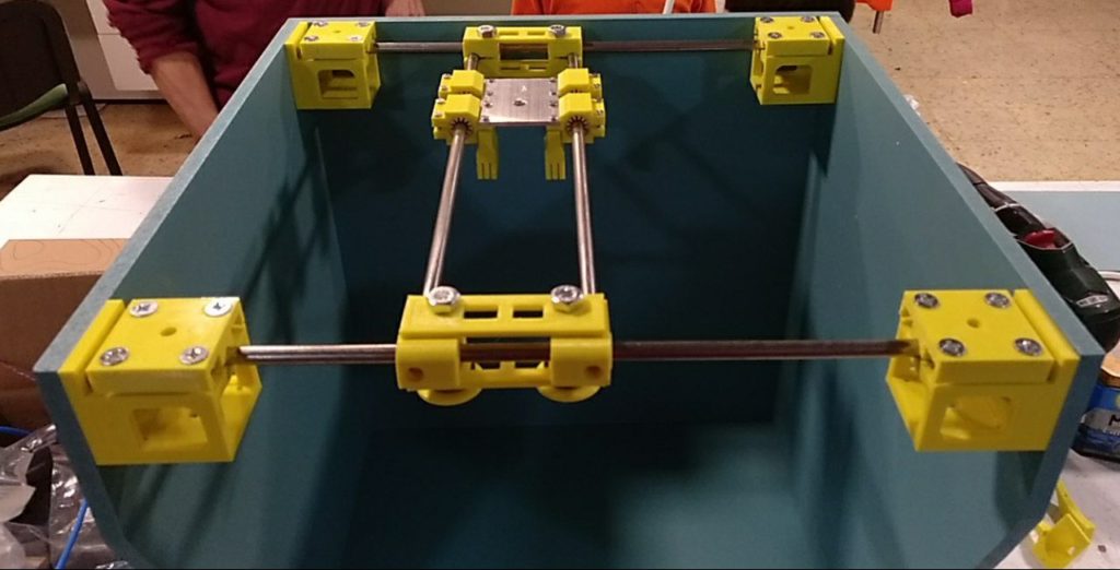
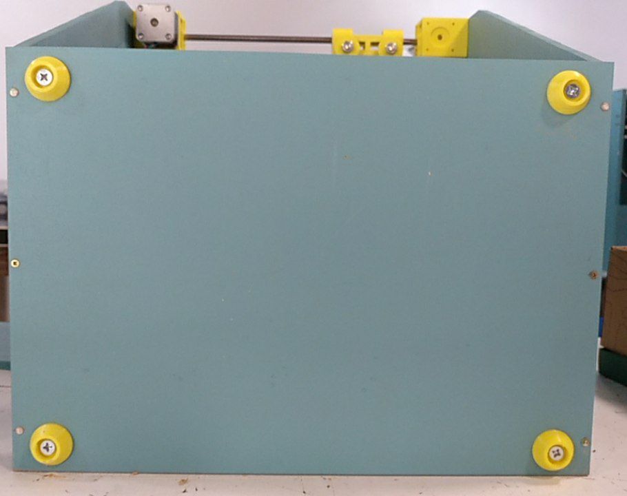
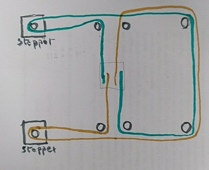
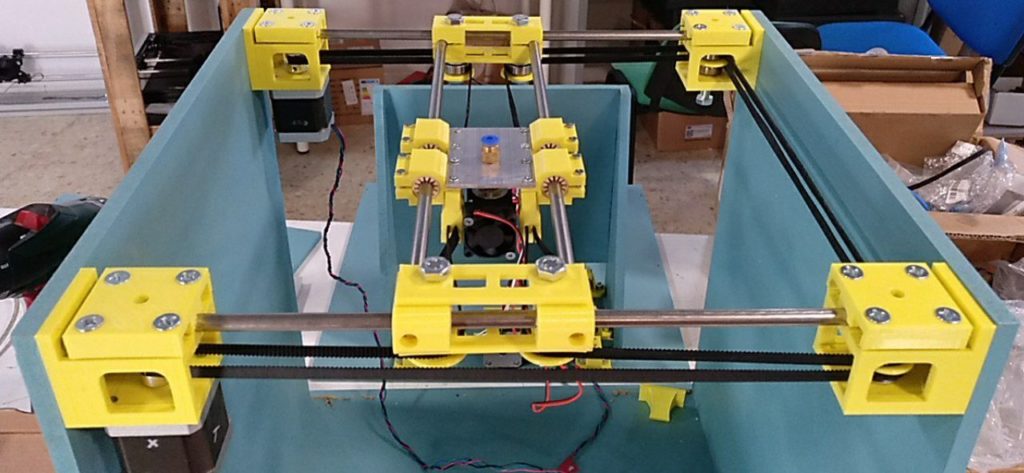
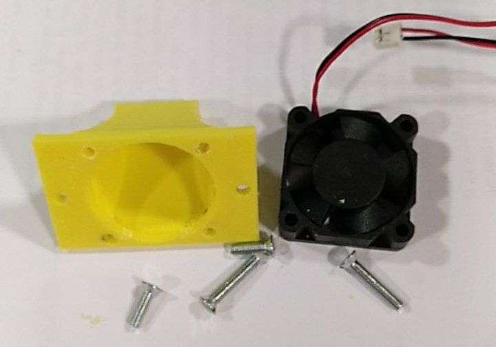
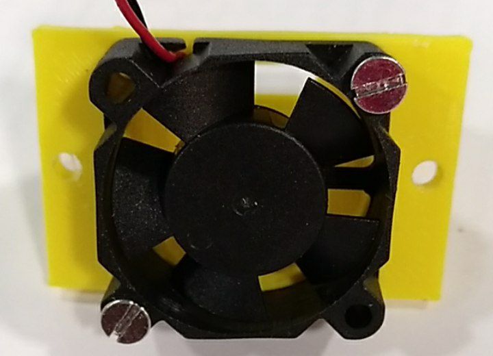
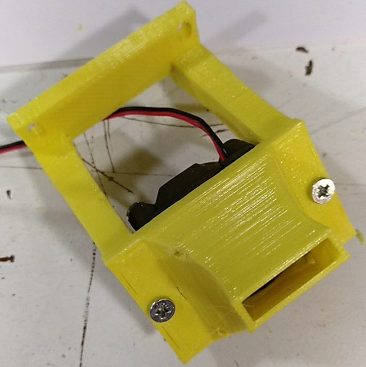
The head plate mountedThe XY system mountedMount the feet (with M6x20 screws)Now mount the belts according to this sketchThe belts mountedPrepare M3 screws to mount the 25mm fan.Mount the fan on the air guideMount the air guide on the holderMount the fan holder on the head plateLet’s mount the Z system now :cut 2 smooth 8mm diameter bars of 365mm lengthand clean again if necessary with a metal file until the bar gets in
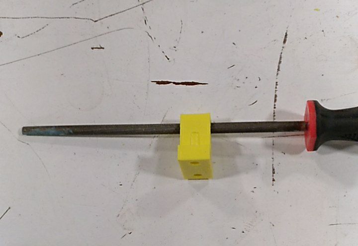
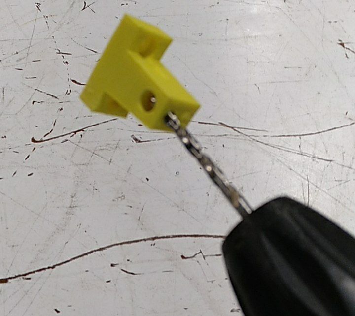
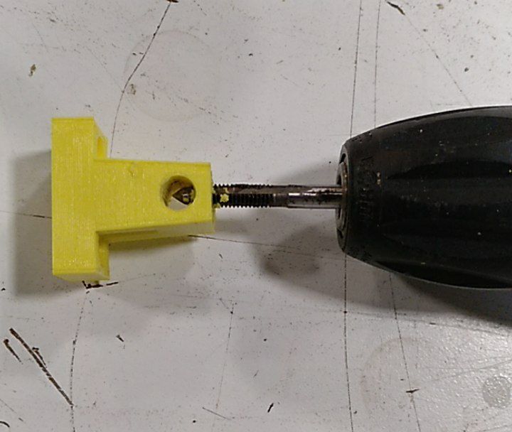
Drill 5mm hole and tap to M6 for the M6 blocking screws
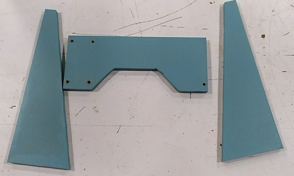
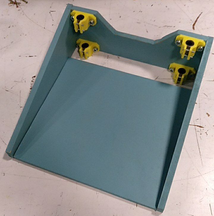
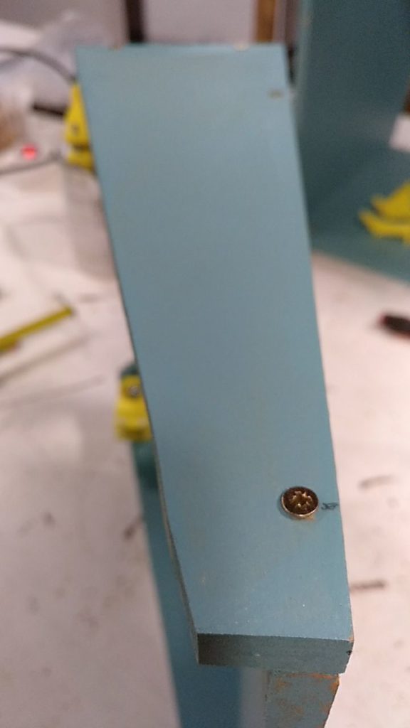
Side plate
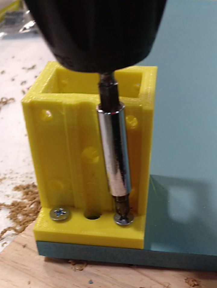
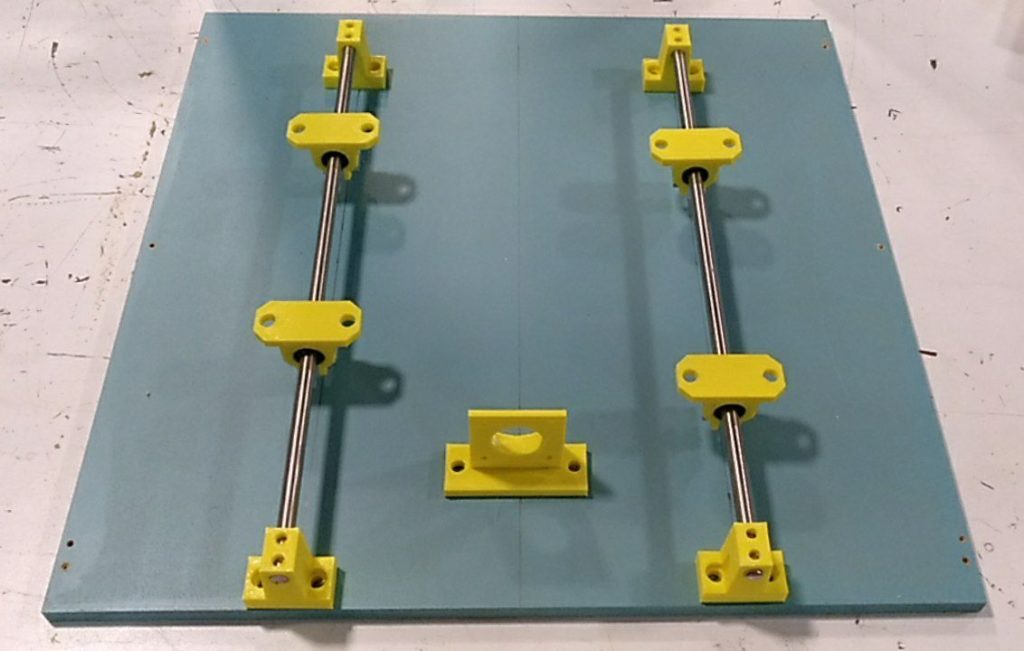
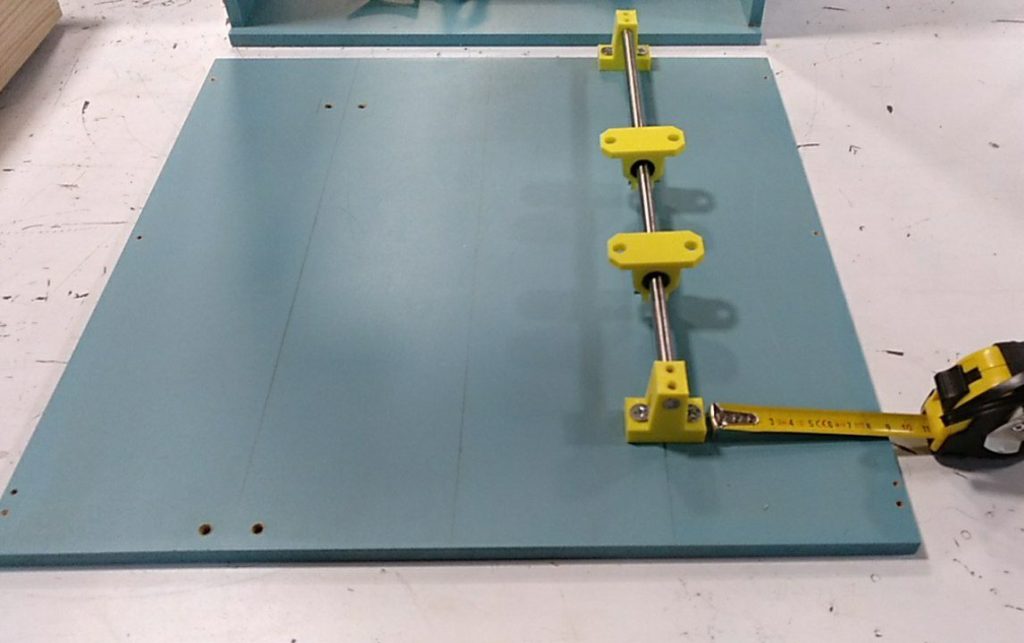
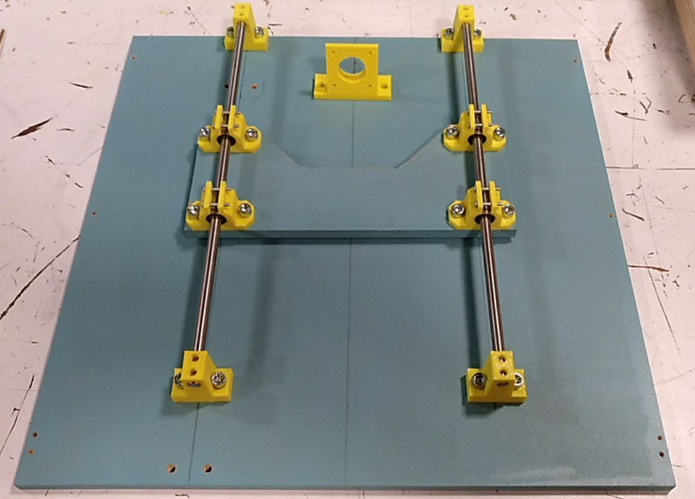
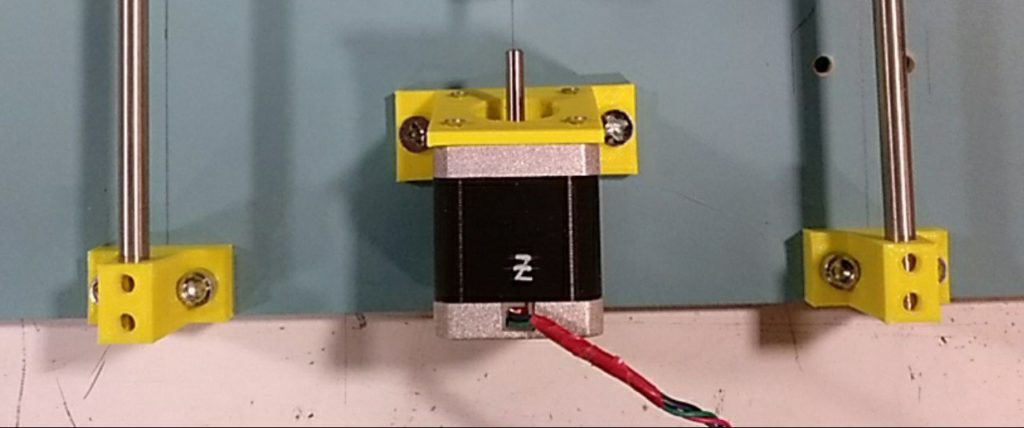
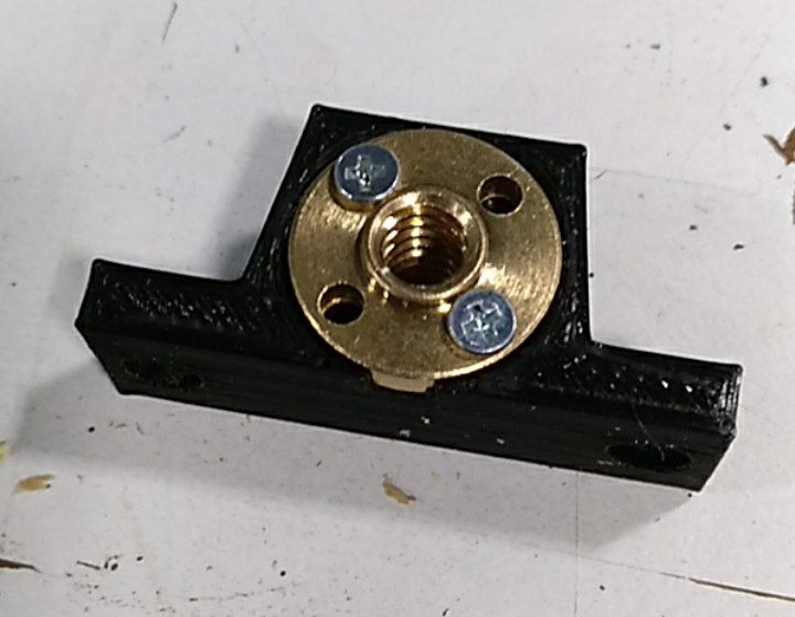
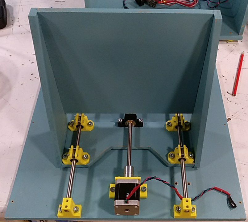
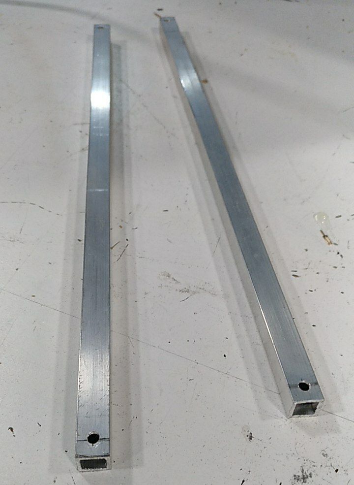
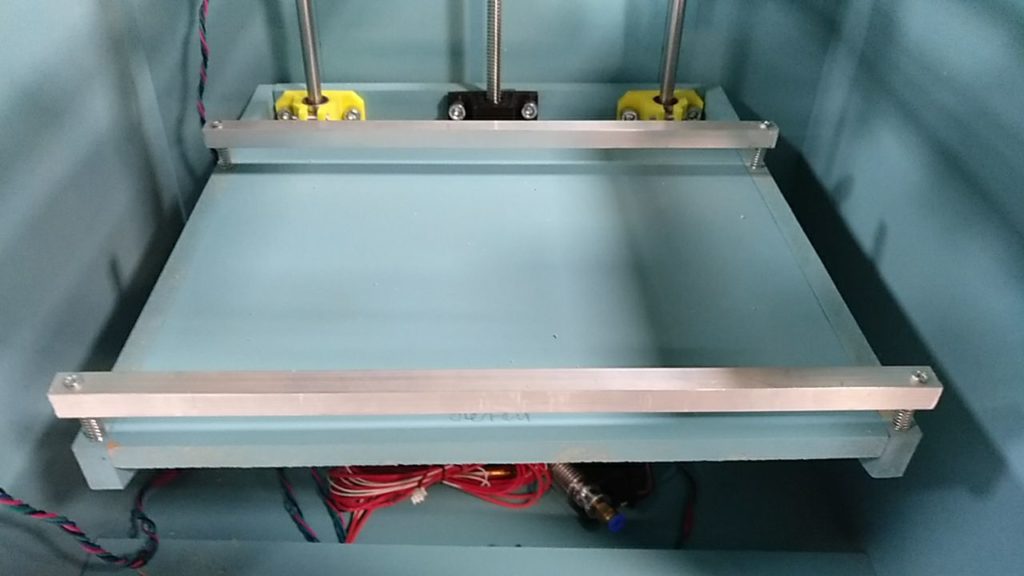
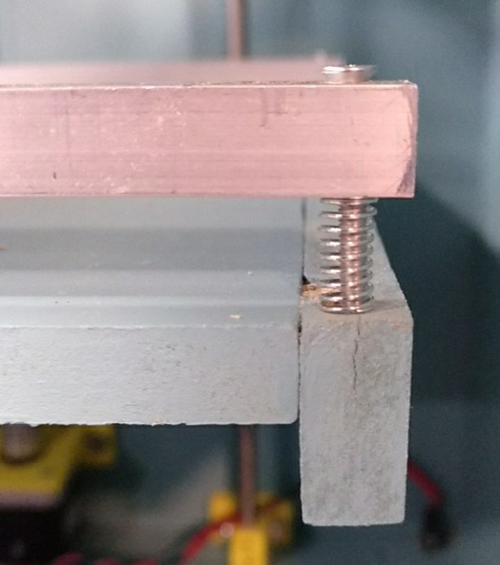
Cut the wood 10mm thick side plates used for the Z system. Cut 2 units.Cut the wood 10mm thick back plate used for the Z system. Cut 1 unit.First screw a first bar a vertical as possible (drill at 5mm and use M6x20 screws)cut and paint the platesDrill 5mm holes and mount the pieces. Start with the 4 linear bearings holders. Screw them partially to absorb the mounting errors. Then mount the second bar. Move it up and down to find its place. Then at the end tighten all the screws.Optionally one can add a squared tableFix it with 3mm wood screwMount the Z motor with 2 M6x20 screws (drill 5mm holes)Mount the z screw on the Z screw holder (drill 2.5mm holes and tap them at M3)Mount the Z screw holder on the Z back plate (with M6x20 screws) and mount the full Z screw system.Cut 2 aluminium bars of section 10mx10mm and 270mm long (just the size of the bed top plate in X direction). Drill 3.2mm holes at the sides, 5mm distance to the borders.Mount the bars like the photograph with 30mm M3 screws and springs. The first one just at the front border and the second one at 18cm back. Be careful to drill the holes using the bars to get exactly the correct distance between them.The 30mm M3 screw with its spring.
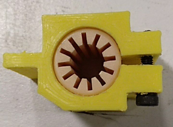
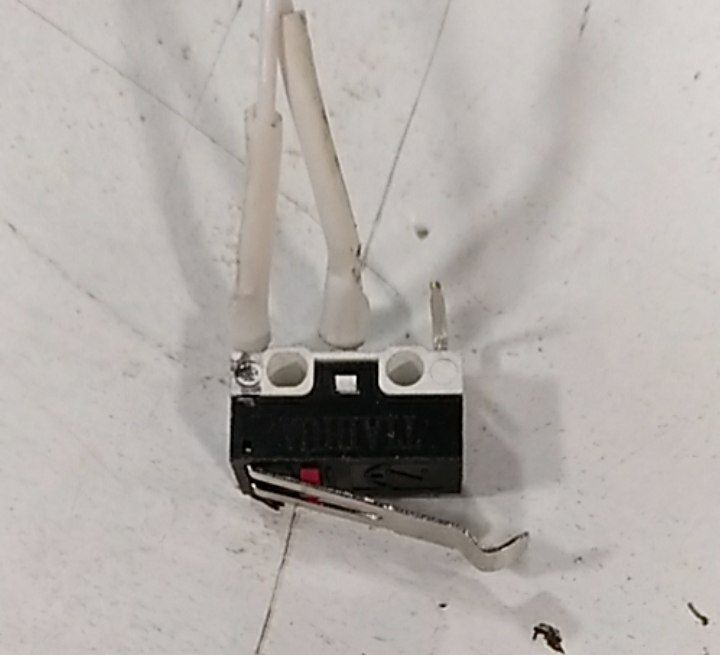
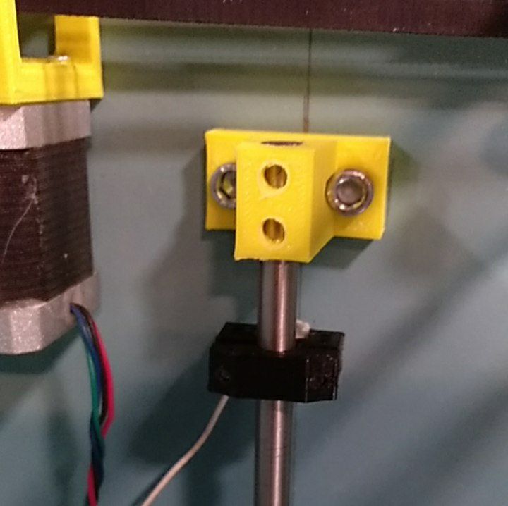
Solder the end-stops
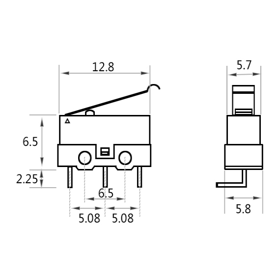
Doc of the end-stops
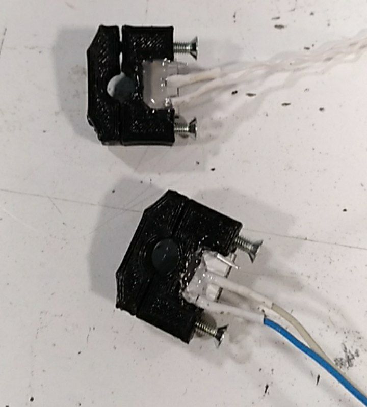
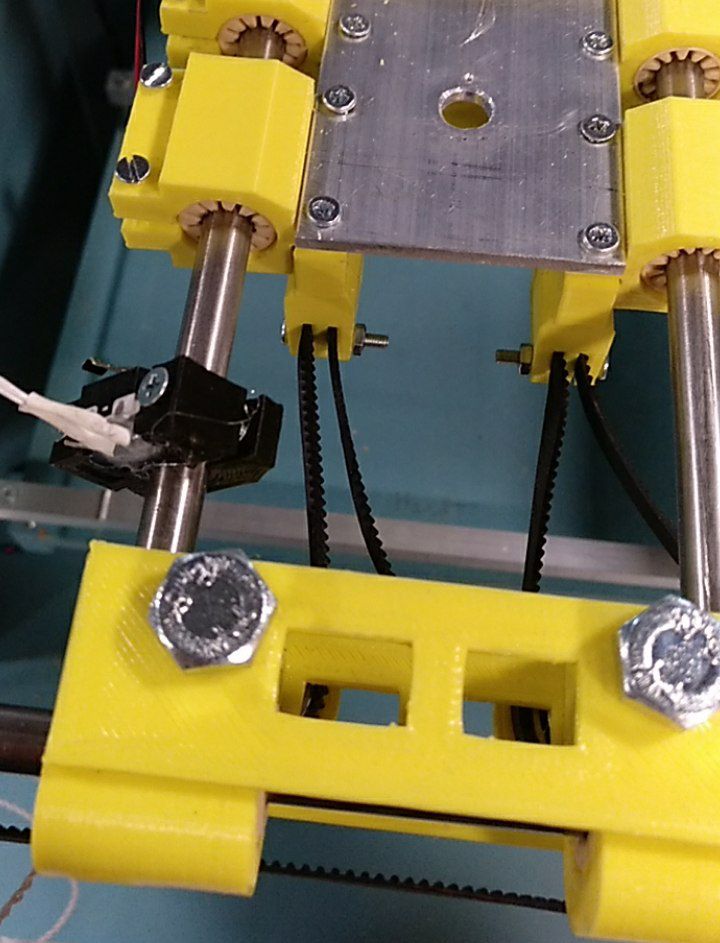
Glue the end-stops on the holders with silicon hot glue.Mount the Y end-stopMount the Z end-stop